Block Diagram Of 555
555 ic lm555 timer ne555 diagram internal schematic block pinout ne556 fairchild modified pinouts working control failure pcb robot following Diagram block 555 computer memory multiplexer decoder towards based complete larger click Ne555 transistor driver
IC 555 Pinouts and Working Explained
Diagram block functional ne555 Introduction to 555 ic with a simple application 10+ functional block diagram of ic 555
555 multivibrator timer monostable circuit
Astable multivibrator using 555 timerHow does ne555 timer circuit work Monostable 555 multivibrator working principle and circuit diagram withMagicelectronics: block diagram of "555 timer ic".
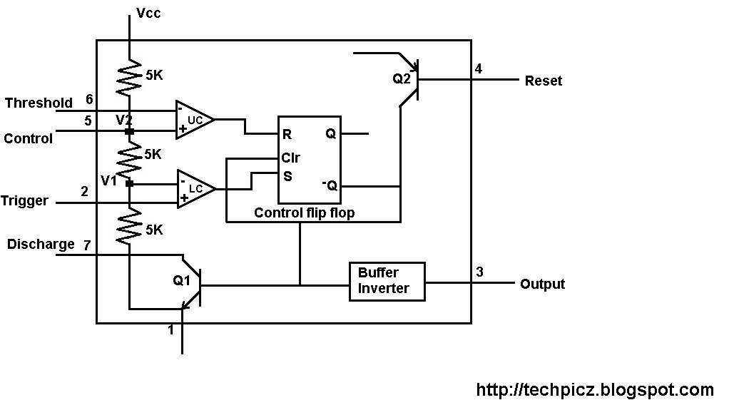
Monstable multivibrator using 555 timerReady to help: functional block diagram of ic 555 555 diagram block control timer internal theory circuit ic interface engineeringTechpicz: functional block diagram of ne555.

555 circuitbasics multivibrator
Block diagram timer ic555 timer – a complete basic guide 555 timer diagram ic block basic circuit complete circuits op guide flip tutorial two flop projects has collectionTimer monostable simplified fig.
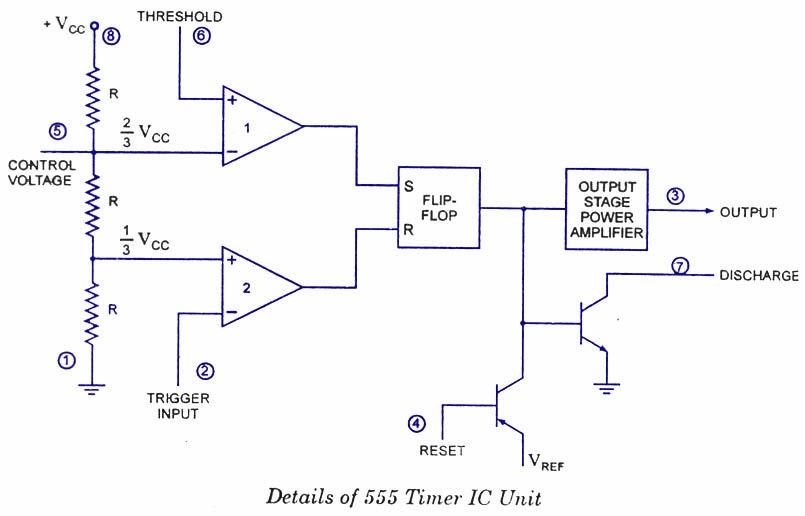
555 timer diagram block circuit chip does ne555 datasheet inside pinout work works eleccircuit look functionIntroduction to the 555 timer Functional block ic ne555555 timer ic diagram block working functional principle internal circuit schematic comparator avr pic ready help.

555 diagram block timer ic led flasher electronics wikitechy
10+ functional block diagram of ic 555Glossary of electronic and engineering terms '555 timer operation' Discrete 555 using transistors (replica of ne555 ic)Introduction of 555 timer ic in monostable mode.
Ic 555 pinouts and working explained(towards) a 555-based computer 555 timer led flasher555 timer diagram ic block circuit transistor electronics do discharge output does logic reset tutorial multivibrator flop flip bistable mode.

555 timer diagram multivibrator monostable ic internal working block circuit animation principle
Ne555 555 timer flop dil8 circuits quora interno modes diagrama integrado circuito circuitry comparators astable transistor temporizador minuterieDiagram block ne555 internal structure 555 timer ne555 principleIc timer 555 diagram block introduction working configuration.
555 timer ic: introduction, working and pin configuration555 timer ic diagram block astable multivibrator circuit using internal .

Ne555 Transistor Driver

Introduction of 555 timer IC in monostable mode
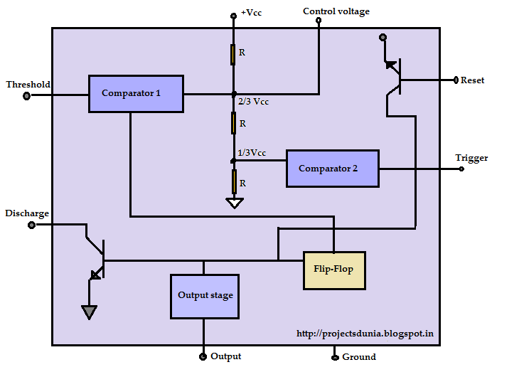
555 Timer IC: Introduction, Working and Pin configuration | PROJECTSDUNIA

555 Timer LED Flasher - Block Diagram of IC 555 Timer - By Microsoft

Monstable Multivibrator using 555 Timer

How does NE555 timer circuit work | Datasheet | Pinout | ElecCircuit.com
Ready to help: Functional Block Diagram of IC 555

magicelectronics: Block Diagram of "555 TIMER IC"